
© Ali AlSaibie, PhD.
© Ali AlSaibie, PhD.
Next: Part I L5 - GPIO
Give an overview standard microcontroller peripherals
Become familiar with the STM32Nucleo and its peripherals
Become familiar with reading a microcontroller datasheet
Remember that a micro-controller is more than just a microprocessor. Subsystems within the micro-controller that are dedicated to a specific functionality are referred to as a peripheral, for example:
An MCU communicates with a digital accelerometer through the I2C protocol. It will need an I2C Peripheral.
An MCU reads an analog temperature sensor, the analog sensor needs to be converted to digital. It will need an ADC Peripheral.
An MCU needs to keep track of time, count how many seconds have passed between events. It will need a Timer Peripheral.
There can be multiples of the same peripheral on one MCU (e.g. 3 ADC peripherals)
A microcontroller encompasses a CPU core, memory, system clock, power management and a host of peripherals.

Here is a list of some common peripherals found on many modern microcontrollers.
GPIO: General Purpose Input Output
Basic input-output interface
UART: Universal Asynchronous Receiver Transmitter
Serial communication protocol
SSI: Synchronous Serial Interface
Serial communication protocol
JTAG: Joint Test Action Group
Programming and debugging interface
USB: Universal Serial Bus
High Speed Serial Communication
ADC: Analog to Digital Conversion
Convert Analog Signals to Digital Values
I2C: Inter-Integrated Communication
Serial Communication protocol
CAN: Controlled Area Network
Vehicle Communication Standard
Timers: Clocked counters
Keep track of time within microcontroller
Ethernet: Network Communication Interface
Local Area Network Communication Protocol
Analog Comparators
Device that compares two voltages or current and outputs a digital signal
PWM: Pulse Width Modulation
A pulsed digital output, used for communication and control of analog devices
Peripherals have their own processing logic/resources, they don’t compete with the CPU: They don’t share your program execution resources Let’s introduce a few common peripherals at a high level
GPIO
ADC
UART
Timers
We will go through each one in a bit more detail later in the course
GPIO: General Purpose Input-Output
Provides most basic way to interface MCU with the outside world. Things you can do through GPIO (not limited to):
Connect a GPIO pin to a switch and read the state of switch press
Connect a GPIO pin to an LED and turn the LED on/off
Connect a GPIO pin to a relay and switch a machine on/off
Connect to an “interrupt” pin, to register when an external event happened.

Pin PA1 and PA0 are both configured as GPIO pins.
PA1 is read as "Port A Pin 1", and similarly PA0 is read "Port A Pin 0" PA1 is set as an output pin while PA0 as set as an input pin.
When PA1 is set High (Logic 1) the LED turns on. And when the switch SW is pressed, pin PA0 reads logic 1 (High). An output pin is set and an input pin is read. The GPIO Peripheral usually has multiple ports, which have multiple pins.
ADC: Analog-to-Digital Convertor
An analog signal has an infinite resolution. While a digital signal has finite resolution. An analog signal is continuous: (e.g. temperature sensor, strain-gauge scale) while a digital signal is discrete: (e.g. High/On or Low/Off)
The ADC peripheral of a microcontroller helps convert an analog voltage signal to a digital value.
The ADC peripheral comes with configurable features, such as:
Different resolution settings: ±1mV? ±8mV? ±12mV?
Number of samples: It can take multiple fast readings and return the average result.
Range: Adjusting the range to capture the expected signal range can maximize resolution. Is the signal expected to be in the 0-3V range? 0-5V? 0-0.9V?

The program can check for the latest value (polling), or the ADC peripheral can be set to notify the program code (via interrupt), that a new value is ready to be read.
UART: Universal Asynchronous Receiver/Transmitter
UART is one of several communication protocols used on MCUs. It is used for communication between PC and MCU (e.g. Arduino: Serial.print()). But an intermediary UART-to-USB is used here. UART is also used for: RF wireless communication, sensors (GPS sensors), old dial-up modems.
Asynchronous means that communication not synchronized between parties. The sender does not have to wait for the received or a broker to manage when to send or when not to send. At a minimum, two lines are required between devices (in addition to power and ground)
One Line for Sending (TX: Transmitter)
One Line for Receiving (RX: Receiver)
Modern MCUs have USART instead (S: Synchronous, so both async and syn modes are supported)

Here pins PA11 and PA12 are configured for the UART peripheral, PA11 is configured as a transmit (TX) pin and PA12 is receive (RX) pin.
The GPS signal receives signals from visible satellites, converts location and time data to a series of characters, then sends this information through its TX pin. Note that the TX pin of the GPS sensor is connected to the RX pin of the MCU. The MCU can perhaps send configuration commands through PA11: TX
Timers
Timers provide a way to keep track of time (surprise!). They keep a counter that ticks at a configured rate, this can be used to:
Tell the time or elapsed time.
E.g. When you call delay(500); a timer peripheral is used
Call a function at a specific and deterministic rate.
E.g. Essential in applied control systems
Generate a signal with a specific frequency & on/off time ratio
E.g. Generate a square wave, PWM or PPM signal
Record the time when an external or internal event occurred
E.g. Register the frequency of a square wave signal
We will go through each of these peripherals in more detail in the following lectures and labs.
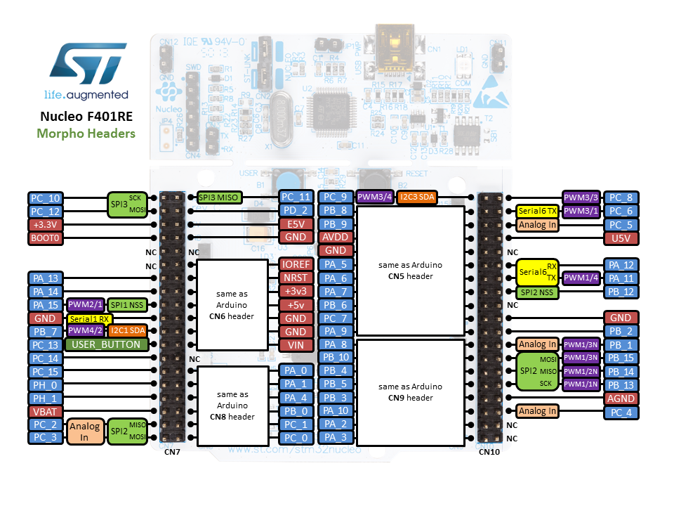
The following image shows the Morpho header pins on the STM32Nucleo F401RE and some of the alternate functionalities they have, this image is referred to as the pinout diagram. Looking at the pinout we notice a few peripherals such as: SPI, GPIO, PWM (TIMER), I2C, ADC, UART.
But how do we know what peripherals are available on a specific MCU? Well, we refer to the datasheet. The microcontroller datasheet contains all the key information about all the bells and whistles that come in the microcontroller.
Information such as: speed, memory size, power consumption, electrical ratings, peripherals and their specifications, chip variants and their pins and physical layout, the dimension of the chip for manufacturing purposes, the functionalities of every pin, ordering information and much more.
The first or cover page of the datasheet usually contains a summary of the features. An engineer can tell if a certain MCU is suitable or not, just by looking first at the datasheet cover page.
Let’s look at the first page of the STM32F401RE microcontroller. STM32F401RE is the MCU on the STM32 Nucleo F401RE board we use in this course. A datasheet is often provided for a sub-family of microcontrollers such as SMT32F401xD/E, where x can stand for different letters/numbers representing different variants. D/E: Includes part numbers that end with D and E

Next: Part I L5 - GPIO