
© Ali AlSaibie, PhD.
© Ali AlSaibie, PhD.
In this prelab we will exercise basic debugging on the microcontroller, then we will experiment with programming the microcontroller GPIO on a low-level without any added headers. Debugging features are applicable whether we choose to program the microcontroller on a low-level, or higher abstraction level. The debugging features are independent of the framework used.
First let's create a new PlatformIO project, but this time, let's select the STM32Cube framework. Which is a collection of headers including functions and macros provided by ST for their line of STM32 microcontrollers.
Create a new project. Name it Prelab3, select the ST Nucleo F401RE board and the STM32Cube framework.
Add the src_filter instruction in the platform.ini file as shown. Note that we will technically be programming in C, not C++. Hence the *.c extension
[env:nucleo_f401re]
platform = ststm32
board = nucleo_f401re
framework = stm32cube
src_filter = -<main*.c> +<mainE1.c>
You will notice that no source files exist under src. Place the source files supplied with this prelab assignment into the src folder. You can find them here.
Alternatively, you can create a new source file by right clicking on src folder -\> New File and naming it with *.c extension.
Let's familiarize ourselves with the debugging process now. Debugging allows you to step through the code one line at a time or down to one assembly instruction at a time.
This helps you to troubleshoot your code and keep track of your algorithm at the step level you choose. This is a powerful feature when developing programs, as well as a way to gain more experience and knowledge in programming and program behavior.
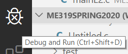
With your project created, source files added, and src_filter set in the platform.ini file for mainE1.c. Go ahead and click on the Bug symbol on the left task pane
Then on the top left, open the DEBUG AND RUN drop down menu and select the PIO Debug (you_project_name) debug configuration, then hit the green play button.
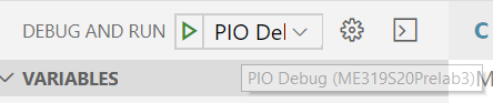
The code will compile mainE1.c in debug mode, flash it into the microcontroller and once loaded and started, it will pause the program inside the main() function. Note that when you upload regularly without debugging, the MCU boots and runs the program normally without pausing.
Now you are ready to debug and step through the code.
Explore the different parts of the debugging workspace. On the left, you see a tab for variables, one for peripheral registers, one for watch variables, etc. On the top right corner there is the debugging step control, where you can resume the program, pause, stop, step through the code, step in and step out of functions, and restart.
Carryout the following steps to explore the debugger
Go to the debugger step control pane and hit the step over button (F10), the program will execute one line inside main() and pause, press step over several times and observe what happens to the variables under the variables watch.
Go to the watch tab and add an expression (+ button), type g_a*3 as the new expression, you will notice that the watch output will be 3*g_a. You can use the watch tab to keep track of variables and expressions, and as you just did, make up your own expressions.
Note that under the peripherals tab, you can see the values inside all the peripheral registers grouped by bitfields as they are laid out in the reference manual.
When you reach the increment(&c) function line, as you step over, click on the step into button (F11), this will take you inside the function call instance. To jump out of the function click on the step out button (Shift+F11).
Note that step over does not take you inside the functions. You have to specifically step in functions. Or you can setup a breakpoint inside the function.
Let's explore the use of breakpoints now.
To the left of the line numbers in the editor, go to line 12 and to the left of it click once in the empty white space, a red dot will appear. This read dot is a breakpoint. This will let the debugger stop the program once it's reached. Click on Continue (F5), your program will continue executing until a breakpoint is reached. If you did not have a breakpoint and you click continue (F5), your program will continue executing until it terminates.
Click Restart (CTRL+Shift+F5) to restart the program, then carryout the following step to explore the use of breakpoints
Add a breakpoint at line 13, then right click on the breakpoint and select edit breakpoint, then type the expression c == 2, as shown and hit enter. Then press continue (F5)
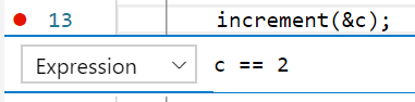
You will notice that the program continues and stops when the variable c becomes equal to 2. You can also choose to have the breakpoint activate when a specific line has been hit a number of times, by choosing Hit Count instead of Expression.
The following part assumes you have reviewed Part I Lecture 5 GPIO
In class, we reviewed the different ways we can program a blinky routine on the STM32Nucleo. Let's test the low-level example (without headers) and use the debugger to explore what happens to the values in the respective registers. Go to the platform.ini file and change mainE1.c to mainE2.c in the src_filter. In order to compile example 2 instead.
mainE2.c /* Look Ma!, no headers */
/***
* Blinky Program - LED connected to PA5
* */
#define GPIOARCCR (*(volatile int *)(0x40023800 + 0x30))
#define GPIOAMODER (*(volatile int *)0x40020000)
#define GPIOAODR (*(volatile int *)(0x40020000 + 0x14))
int main(void) {
/* Step 1: Enable GPIOA Clock */
GPIOARCCR |= 1; /* Ref RCC_AHB2ENR register */
/* Step 2: Set Port A Pin 5 as Output */
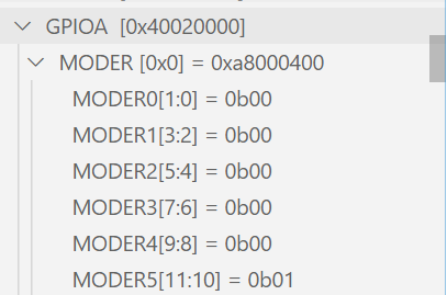
GPIOAMODER |= (1 << 10); /* Ref GPIOx_MODER register */
while (1) {
/* Step 3a: Set LED Pin High */
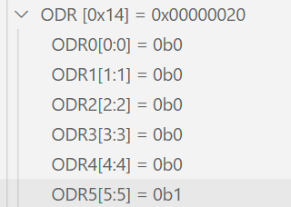
GPIOAODR |= (1 << 5); /* Ref GPIOx_ODR register*/
/* Dumb Delay: wait x number of clock cycles */
for (int k = 0; k<500000; k++){__asm("nop");}
/* Step 3b: Set LED Pin Low */
GPIOAODR &= ~(1 << 5); /* Ref GPIOx_ODR register*/
/* Dumb Delay */
for (int k = 0; k<500000; k++){__asm("nop");}
}
}Upload the code through the debug mode presented above, then step through the lines and observe the changes that occur in the respective registers under the peripherals pane. Specifically,
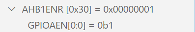
At step one, we enable the GPIO A clock. To do that, we change the RCC_AHB1ENR register's GPIOAEN bitfield. Which is bit 0 of the RCC_AHB1ENR register. (You can find it under RCC Peripheral, or type the name in your keyboard and it will filter the results for you)
At step two, we set GPIO Port A Pin 5 (PA5) to output. For this we manipulate the GPIOA_MODER, Mode Register, bits [11:10]
At step 3a (3b) we set the GPIOA_ODR, Output Data Register, bit 5 to high (low)
Congratulations, you've debugged your first MCU program and executed a low-level blinky routine.
Go ahead and test running mainE3.c, it is equivalent to mainE2.c, but uses the macro definitions for the register addresses and bitmasks from the header "stm32f401xe.h", which is supplied by the board manufacturer, ST, through the PlatformIO IDE.
mainE3.c #include "stm32f401xe.h"
/***
* Blinky Program - LED connected to PA5
* */
int main(void) {
/* Enable GPIOA Clock */
RCC->AHB1ENR |= RCC_AHB1ENR_GPIOAEN; /* Ref RCC_AHB2ENR register */
/* Set Port A Pin 5 as Output */
GPIOA->MODER |= (1 << GPIO_MODER_MODE5_Pos); /* Ref GPIOx_MODER register */
while (1) {
/* Set LED Pin High */
GPIOA->ODR |= (1 << GPIO_ODR_OD5_Pos); /* Ref GPIOx_ODR register*/
/* Dumb Delay: wait x number of clock cycles */
for (int k = 0; k<1000000; k++){__asm("nop");}
/* Set LED Pin Low */
GPIOA->ODR &= ~(1 << GPIO_ODR_OD5_Pos); /* Ref GPIOx_ODR register*/
/* Dumb Delay */
for (int k = 0; k<1000000; k++){__asm("nop");}
}
}So instead of referencing the registers addresses manually, the "stm32f401xe.h" headers has handy structs and offsets defined for each register block. And instead of doing bit shifting, the bitmasks for each bitfield/s is/are defined by macros explicitly. Take some time to read the stm32f401xe.h header file.
Note that we have not used any of the STM32Cube HAL drivers. We could have done the above using the SPI framework, which is a subset of STM32Cube, or the CMSIS framework which is an ARM specific framework.
The last two examples produced equivalent code and almost identical binary file. The STM32 family also comes with a Standard Peripheral Library as well as STM32Cube HAL library. The latter is more abstract and covers the full range of STM32 microcontrollers, from the low energy STM32F0 to the STM32F7. It is the most widely used way to program and interface with the STM32Cube as of today.
The below example shows how to use the the STM32Cube library to generate a blinky routine. Note that no registers are referenced. Instead of consulting the reference manual to program the microcontroller, you would instead reference the STM32 HAL and LL Drivers document.
mainE4.c #include "stm32f4xx_hal.h" /* We don't include the specific stm32f401xe header, but just the HAL */
#include "stm32f4xx.h"
#define LED_GPIO_CLK_ENABLE() __HAL_RCC_GPIOA_CLK_ENABLE()
int main(void){
HAL_Init(); /* Initialize the HAL Drivers */
LED_GPIO_CLK_ENABLE(); /* Enable GPIO A Clock */
GPIO_InitTypeDef GPIO_InitStruct;
GPIO_InitStruct.Pin = GPIO_PIN_5 | GPIO_PIN_4;
GPIO_InitStruct.Mode = GPIO_MODE_OUTPUT_PP;
GPIO_InitStruct.Pull = GPIO_PULLUP;
GPIO_InitStruct.Speed = GPIO_SPEED_FREQ_HIGH;
HAL_GPIO_Init(GPIOA, &GPIO_InitStruct); /* The pin configuration is done through a function */
while (1)
{
HAL_GPIO_TogglePin(GPIOA, GPIO_PIN_5); /* HAL provides a toggle pin function */
HAL_Delay(1000); /* As well as a delay function (milliseconds) */
}
}
void SysTick_Handler(void) {
HAL_IncTick();
}The first function in main is HAL_Init(), this would configure some common peripherals including the system tick timer, which allows for using the HAL_Delay() function.
To enable the GPIOA, there is a specific function in the library __HAL_RCC_GPIOA_CLK_ENABLE() that can do that.
To configure a GPIO, it would be done by assigning values to the struct GPIO_InitStruct and passing it to the function HAL_GPIO_Init() which would configure any GPIO port.
There are several functions that help interface with the GPIO. To toggle a pin state for example you can use HAL_GPIO_TogglePin(). Consult the STM32 HAL and LL Drivers document to familiarize yourself with the type of functions available.
The Arduino implementation on STM32 (stm32duino) does use the STM32Cube drivers (library) in the middle. And if there were functions not available in the Arduino implementation for STM32, you can always reference and use the HAL functions in tandem, but be aware that the Arduino framework may be overriding your settings in some circumstances, so you would have to do some homework when combining Arduino and STM32Cube.