
© Ali AlSaibie, PhD.
© Ali AlSaibie, PhD.
In this lab we will learn how to implement a feedback controller, in order to perform both speed and position control on a conventional brushed DC motor. We will apply what we learned about timers in Lab 4 to implement a feedback control structure.
STM32 Nucleo F401RE Board
USB Type A to USB Mini-B Connector
X-Nucleo-IKS01A2
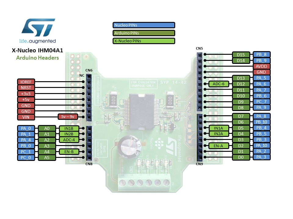
X-Nucleo-IHM04A1
Lab Report Submission Guidelines
A DC motor is a commonly used actuator in numerous systems. A brushed DC motor, which we will be using in this lab, consists of a housing, bearings on which the output shaft is supported, stator (non-rotating part) that encompass the magnets and then the rotor which combines the drive shaft, the coils that current flows through and generate an Electromagnetic Force, the commutator that sends the current to the armature and brushes that force current through the coils.
A common and universally used brushed DC motor driving circuit is known as an H-Bridge circuit. The circuit allows for routing the current from the power supply through the motor by way of operating four switching semiconductors resembling the letter H. A motor driver normally encompasses the H-Bridge circuit along with power and driving logic. As shown on the following figure.
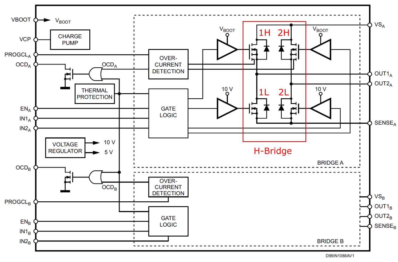
In the figure, OUT1 and OUT2 are connected to the motor terminals. IN1 and IN2 are inputs from the microcontroller. The A and B denote two Full H-Bridge drivers on the chip, capable of driving two bidirectional brushed DC motors. The transistors used in the H-Bridge circuit are N-Channel Power MOSFETs (NFETs). EN is a driver enable input, this pin must be set to HIGH in order to enable output to the motors.
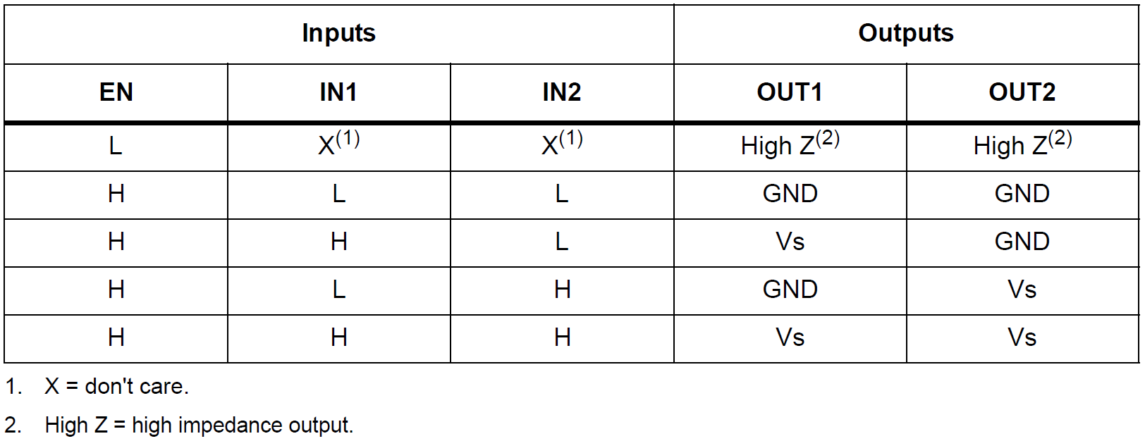
The gate logic of the motor driver chip switches the NFET pairs according to the inputs IN1 and IN2. If IN1 is high and IN2 is low, OUT1 is connected to Vs and OUT2 is connected to GND. Vs is the motor supply voltage. If IN1 is driven by a PWM signal, the motor will be supplied with a voltage matching the frequency and duty cycle of the PWM signal. L6206 H-Bridge Truth Table shows the logic of the output pins based on the inputs.
To switch the direction of the motor, then IN1 is set low and IN2 is driven by the PWM signal instead.
Also known as an optical sensor, an opto-interrupter is composed of an emitter, detector and a rotating disk with slots that allow light to go through. As the disk rotates, the light is blocked and unblocked from the detector as the slots come in and leave from in-between the emitter and detector. The disk can be attached to a motor shaft and by observing the opto-interrupter signal, the speed of the motor can be measured. This setup is also referred to as a motor encoder.
The rotary disks can have more than one slot, the more slots there are the higher the resolution in measuring speed and position. A quadrature encoder is one where the rotating part is composed of two offset slotted disks. The offset is normally 90o, this is also known as the phase lag.
Each disk is considered a channel, and when the motor is rotating in one direction, one channel will lead the other by a quarter of a period and vice versa for the other direction. A quadrature encoder can be used not only to measure speed and position of the motor but also the direction of rotation, Figure Quadrature Encoder.

In this lab, we will be using a quadrature encoder to measure the position, speed and direction of the motor.
Timers are essential in achieving the required structure for real-time control. We know that we can use a timer to generate periodic function calls, or to generate a PWM signal or to read the pulse counts or frequency of an input signal.
The following list of timers and interrupts will be used:
PWM Timer: This timer will be used to generate a PWM signal on two outputs connected to the motor driver.
Periodic Timer: This timer will be called at a fixed rate to compute the next control action, executing the PID control law.
Input Capture Timer: This timer will be connected to the encoder channels A and B signals and will be used to keep count of the number of pulses and the frequency of the pulses, in order to measure the position and velocity of the motor respectively.
The timers are configured in a similar fashion as done in Prelab 4.
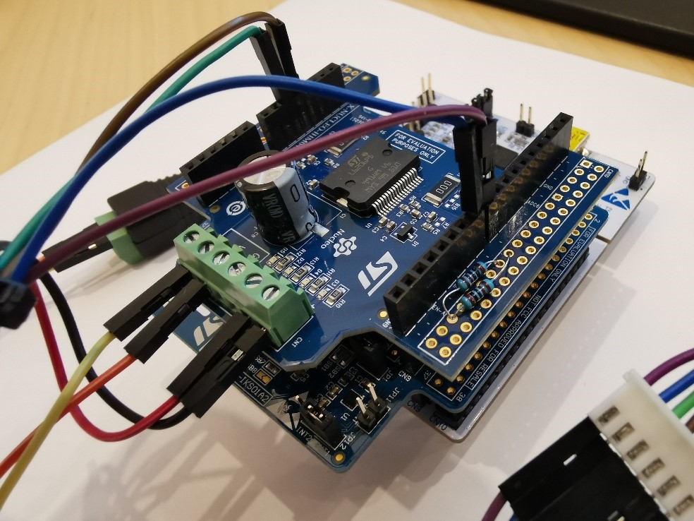
For this lab we will be using the X-Nucleo-IHM04A1 Expansion board, which hosts the L6206 motor driver IC. The board stacks on top of the Nucleo F401RE microcontroller board using the Arduino connection headers. Connect the motor terminals (red and black wire) to Bridge A (A+ and A-) of the board, polarity doesn’t matter, as the motor will just spin in the opposite direction. Connect the 12V power supply to the Input of the IHM04A1 expansion board, but polarity matters here obviously. The expansion board already connects IN1A and IN2A to pins PB4 and PB5 of the microcontroller, respectively. To connect the encoder, connect the blue wire (ENC Channel A) to pin PAB and purple wire (ENC Channel B) to pin PA9. Connect the green wire to GND and the brown to +5V.

The L6206 IC also offers motor current sensing, and the expansion board connects Bridge A’s current sensing output to pin PA_6.
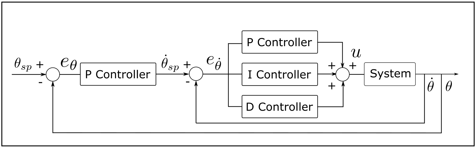
A cascaded controller will be used to control the position of the motor, the inner loop is a PID speed feedback controller, also known as a rate controller, the outer loop is a proportional position controller. As shown on Figure 8 Cascaded Position and Speed Control Block Diagram
The outputs of the microcontroller to control the motor are two PWM signals, in addition to the enable signal. As explained in Section 5, one of the PWM pins should be set to LOW (0% duty cycle), and the other one given a PWM signal with a duty cycle proportional to the supply voltage desired. To rotate the motor in the opposite direction, the latter output is set LOW while the former is given the required duty cycle.