
© Ali AlSaibie, PhD.
© Ali AlSaibie, PhD.
Part A
Part B
Next: Part I L7 - Interrupts
Understand the fundamentals of a timer operation
Overview the application of Timers
Introduce Pulse Width Modulation
Note: the timer operations reviewed in this lecture are based on the STM32F401x MCUs, but they largely apply to all MCU Timers. Names and terms may differ.
This is a mechanical tick counter.
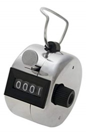
Every time you click the middle button, it increments the counter by one. It continues to count up until 9999 then resets, mechanically, to 0000. Now, replace the mechanical counter by a memory register, and replace the button-clicking-action by an electronic pulse. You now have a digital timer. The size of the counter register (# of bits) and pulse rate: Determine the speed of the count and the reset rate.
If you have an 8bit counter; a counter that counts from 0 to 255 then resets to 0. And you are counting up at a rate of 20Hz. How long does it take for you to count from 0 to 255?
In the context of an MCU, a timer counts up or down, either at a specific rate or in response to an event.
The timer count is stored in a memory register (8, 16, 32bit registers). A 16-bit timer will count up from 0x0000 to 0xFFFF, then rollover to 0x0000. Or it can count down from 0xFFFF to 0x0000 and rollover to 0xFFFF.
The timer can also be configured to rollover at a specific value (or start from one). For example, it can be configured to count to 0xF0E5, then rollover back to 0x0000.
When an MCU has multiple timer peripherals, usually, every timer peripheral can be independently set. The rate of the count can be independently set, the range of the count, the mode and whether it counts up or down, each can be set independently for each timer peripheral.
A timer increments (decrements) in response to a pulse" Rising Edge, Falling Edge, or Both
The pulse can come from a clock source, which can be scaled (prescaler), or from an event signal (e.g. an external button press, encoder, modulated signal).

We would like to have a timer rollover every . If the timer is running at (count rate), what should be the starting count value (timer in count-down mode).
Using timers, we can
Keep track of elapsed time, or wait for a specific amount of time
E.g. When you call delay(500); a timer peripheral is used
Call a function at a specific and deterministic rate
E.g. Essential in applied control systems
Generate a signal with a specific frequency & on/off time ratio
E.g. Generate a square wave, PWM or PPM signal
Record the time when an external or internal event occurred
E.g. Register the frequency of a square wave signal
Let’s look at how each one is achieved...
An 8-bit count-down timer, can be configured to count from a maximum value of 0xFF. Termed the autoload value, since the MCU will load it onto counter at rollover

Rollover period is defined as:
There are several modes a timer can be configured for
Periodic Timer: Internal MCU use
Input Capture: Records when an external input event occurred
Output Compare: Generates an external output waveform
Additional modes can be found on MCUs, but they are usually an extension of the above. In each of these modes, there is always a counter incrementing/decrementing at a specific rate, but their purpose and use are different. Timers, just like other peripherals, operate independently from the CPU. There is no CPU overhead from using timers; except for when accessing timer data.
Period Timer Mode
When used as a general, or periodic, timer, it is a count up/down timer, and counting is done at a set rate.
The timer can be configured to generate a timed interrupt INT (interrupt CPU at a specific rate) when rollover is occurs if counting up, or when it reaches 0x0000 if counting down.
One usage for example would be to configure a timer (rate, count range) to issue an INT at every rollover, then tie this INT to a specific function call. Now you have a periodic function call, use it to control a robot motor for instance.
The timer can also be checked (polled) by the program. One usage example is to configure a timer to run freely and when you want to delay(500ms), you go and take a reading of the timer, and based on the count rate of that timer, wait for a number of counts (keep checking the timer) to occur that would result in 500ms to have passed, then return, effectively pausing the program for 500ms.
Input Capture Mode
In Input Capture mode, you have a timer running with a certain configuration (rate, range, direction), plus, it monitors for an external input event via a pin (Rising Edge, Falling or Both).
When an event occurs, the timer peripheral makes a copy of the count value in the timer register and stores it in a second memory register. This latter register will store the count value of timer for when an event was last detected (or it can be configured to not override that value until the program has read it first).
The timer in input capture mode can also issue an Interrupt to CPU saying “Hey Boss, an event occurred, come down and read the count value for when it occurred” or the interrupt can be tied to calling a certain function.
With this setup you can measure frequency of an input signal for example. By recording the count values for two consecutive signal events, subtract difference and convert to time or frequency.
Note that the timer counter it self keeps running uninterrupted, when an event occurs, a snapshot of the counter value is stored in a different register.

A timer in Input Capture Mode is used with rotary encoders which are sensors for measuring angular position. By measuring the number of events of this encoder signal we can measure the angular position of a knob or motor, and by measuring the frequency of this signal we can directly measure the angular velocity. More on encoders in later parts of the course.

Given the following Timer Configuration. If the detection mode is on Both Edges (Rising and Falling). What is the counter value when the edge detection occurs. Assume the counter restarts every time an edge is detected.

Output Compare Mode
In Output Compare, you have a timer running with a certain configuration (rate, range, direction), plus a fixed value to compare the count value of the timer with.
For example to general a PWM signal which, at the beginning of the period is set high, then somewhere in the middle before the period is ended, the signal is set low. The timer in output compare mode is set such that At the beginning of the count or at rollover, the GPIO output pin is set high. Then when the counter reaches the compare value, the GPIO output pin value is cleared. With this you can create a a variable width pulse (PWM) where the Autoload Value determines signal freq (period), and the compare value determines the duty cycle.
To general a variable frequency signal (Square Wave) the Autoload Value will be set to determine the signal freq, and the compare value is set as autoload value.

By selecting the range (autoload value) in the counter, the count rate and the compare value an output signal can be designed and generated.
Given the following timer configuration. What should be the autoload value for the 16-bit down counter, and the compare value. In order to generate a 100kHz square wave signal.

When we have an analog input to the microcontroller, we can use the ADC to convert to digital, but how about going the other way? Say we want to vary the output voltage to control the brightness of an LED, or the speed of a motor? Microcontrollers work in 1’s and 0’s, how can we achieve a value in between? How can we emulate an analog signal?
The options for emulating an analog signal are:
DAC: Digital to Analog Conversion (Computationally costly)
PWM: Pulse Width Modulation (Simple and easy)
What makes a PWM usable as an emulated analog signal is that many systems (electromechanical specifically) have a low pass filter characteristic to high frequency signals. The don't respond as fast as the signal, they react to the average value of the signal instead.
A variable signal can be generated with one output


Usually with PWM signals, the frequency is fixed for the application, and what is varied is the duty cycle or "pulse width", hence the name Pulse Width Modulation. Modulation meaning being changed/varied.
There are three parameters that define a PWM signal:
Pulse Width (also known as duty cycle)
Period (Frequency)
Voltage

Duty Cycle (or pulse width, but pulse width is defined in time units) is the percentage of time the signal is HIGH (or LOW for inverted logic).

A PWM signal has a fixed frequency that is independent of the duty cycle. The frequency is configured to be a specific value based on the application.

The PWM frequency must be high enough for the AC component to be suppressed by the driven system. This depends on the system being commanded the PWM signal. Also, for driving coils/windings, humming can occur for frequencies in the audible range. So aim for . But too high frequencies are not recommended, as high frequencies result in high switching rates of semiconductors, and if semiconductors are switched at a high rate, they become less efficient (energy loss). Finally, avoid resonant frequencies of the driven system. For example, don't command a motor with a PWM signal that has a frequency that matches the motors resonant frequency.
What is the voltage of the PWM signal below, averaged over 1 cycle?

Here is a simple example, where a pwm signal is generated by the microcontroller to switch the MOSFET and close the motor circuit on/off rapidly. The duty cycle will determine the average voltage sent to the motor, the motor speed is proportional to this average voltage achieved by the PWM signal. Remember that a MOSFET here acts like a water valve, the PWM signal simply controls the lever, electrons flowing through the motor are like water passing through a pipe and watermill. This circuit only controls the motor speed in one direction. To control the motor in two directions an expanded circuit is needed, we will cover this in later parts of the course.

On the STM32F401x family of microcontrollers there is a dedicated PWM functionality on timer peripherals, as well as a dedicated PWM module separate from Timer peripherals.
Simple Implementation
Using Output Compare Principle
32-bit or 16-bit timer
Provides PWM on all timers/channels
On Advanced Control Timer 1
Combined in single action or complementary pairs
Provide Dead-band delays (prevents shoot through; shorting)
Timer synchronization of PWM blocks
16-bit timer
The STM32F401RE has up to 11 timers

Timers interface with pins through channels. On STM32F4x, a timer has up to four channels. There is a specific pin associated with each channel and a pin might be associated to more than one timer. For Example: Look at PA2 and PA3 in the following table.
